
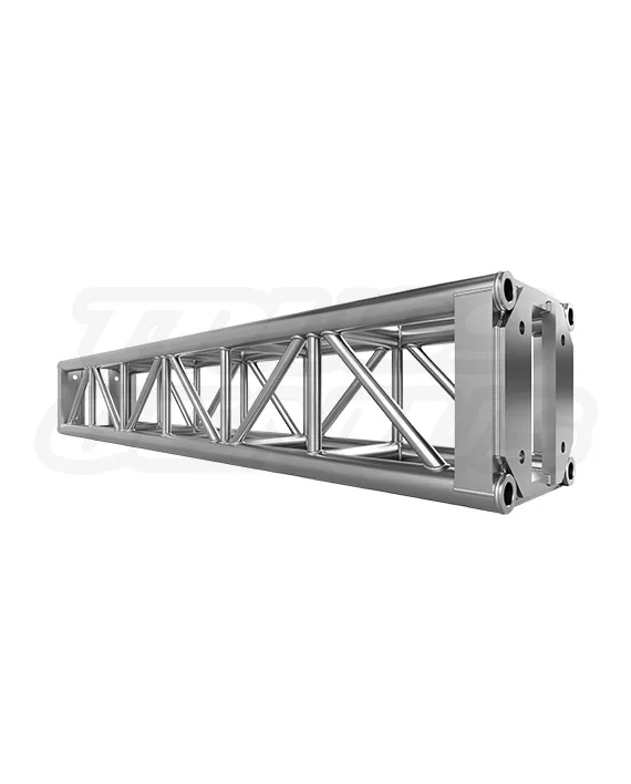
EVT12S-6FT
$930.00 Original price was: $930.00.$699.00Current price is: $699.00.
EVT12S-6FT — 6-Foot Truss Section – 12″ x 12″ Heavy-Duty Square Aluminum End-Plate Truss
Dimensions & Specs
Overall Length: 6.0 ft (1.82 m)
Overall Width: 12 in (304.8 mm)
Type: Heavy-Duty Square Aluminum End-Plate Truss
Construction
Material Type: Aluminum Alloy EN AW-6061 T6
Main Tubing: 1.96 in (50 mm) OD / 0.11 in (3 mm) Wall Thickness
Brace Tubing: 0.98 in (25 mm) / 0.11 in (3 mm) Wall Thickness
Connection Type: End-Plated Nut and Bolt (Heavy-Duty Bolted Truss)
Finish & Features
Surface: Aluminum Brush Finish
Certification: TUV Certified
Included: 4x Grade 8 Bolts, Nuts, and Washers
Weight: 37.5 lb (17 kg)
In stock
EVT12S System Knowledge Center
6 Ft Square Box Truss End Plate Section.
A 72 Inch Straight Section for End-Plate Box Truss Systems.
The EVT12S-6FT is a 72-inch brushed aluminum straight section for standard 12-inch end-plate box truss systems. It suits longer straight runs where a single six-foot member is specified. Allowable loading depends on the complete system, including span, supports, connections, orientation, and applied loads.
Product Facts
Product Overview
A 72-Inch Straight Section for End-Plate Box Truss Systems.
This six-foot component uses an end-plated nut-and-bolt connection. Listed construction includes EN AW-6061-T6 aluminum, 50 mm main tubing, and 25 mm diagonal brace tubing. Evaluate all loading and connection requirements at the completed-system level.
Application Uses
For End-Plate Truss Systems Using A 72-Inch Straight.
This 72-inch brushed aluminum section may be specified within completed end-plate box truss systems for production, exhibition, technical, and installed applications. Confirm the completed system’s span, supports, connections, orientation, attachment points, environmental conditions, and applied loads before use.
Included Hardware
Listed Hardware for One Four-Point Connection.
The product data lists four Grade 8 bolts, four nuts, and four washers. Confirm fastener requirements at every actual joint, including bolt length, condition, engagement, and the applicable manufacturer tightening procedure.
Technical Reference
EVT12S-6FT Truss Section Specifications.
Identification
Product Details
Dimensions
Overall Size
Material and Tubing
Construction
Connection Context
System Interface
System Compatibility
For Standard 12-Inch End-Plated Truss Systems. Verify Every Connection.
This section is identified for standard 12-inch end-plated truss systems. Exact fit with other systems is not guaranteed. Before combining components, verify end-plate dimensions and thickness, bolt-hole positions, chord alignment, hardware, fastener engagement, and completed-joint seating.
Assembly Overview
Align the End Plates. Install and Check All Four Fasteners.
Assembly should be performed by personnel qualified for the truss system in accordance with applicable manufacturer requirements. This outline provides neither torque values nor installation approval.
Engineering Reference
Load-Span Reference for Completed EVT12S Truss Runs.
All truss loading calculations are based on a completed compatible 12 x 12 aluminum-truss run supported or suspended at both ends, under one stated static-load alternative. The values below do not rate an individual straight section, plate, or six-foot truss segment. A section changes the overall length and adds bolted joints; it does not increase the completed system’s allowable capacity.
| Load Case | Unit | 10 ft 3.05 m | 20 ft 6.11 m | 30 ft 9.14 m | 40 ft 12.23 m |
|---|---|---|---|---|---|
| Uniformly Distributed Load | lb/ft | 472 | 115 | 60 | 31 |
| Deflection | in | 0.21 | 0.65 | 1.63 | 2.68 |
| Center Point Load | lb | 2,710 | 1,206 | 580 | 272 |
| Deflection | in | 0.20 | 0.56 | 1.31 | 2.04 |
| Third Point Loads | lb each | 1,744 | 888 | 600 | 442 |
| Deflection | in | 0.32 | 0.68 | 1.48 | 2.62 |
| Quarter Point Loads | lb each | 1,110 | 633 | 428 | 308 |
| Deflection | in | 0.33 | 0.68 | 1.54 | 2.54 |
Table assumptions: The reference evaluates unbraced truss configured as a simply supported beam. The primary analyzed spans were 10 ft, 20 ft, 30 ft, and 40 ft. If CPL, TPL, or QPL loading occurs at a truss connection, a minimum of two chords is assumed to support the vertical load.
Not included: Shock loads, dynamic loads, and resultant horizontal rigging forces, including forces from bridles or baskets. UDL applies only when the load is evenly distributed across the entire span. Published load cases are alternatives and are not additive.
Licensed structural-engineer review is required for every truss system. These values are general planning reference only and do not approve or rate an individual straight section, a completed lighting plot, a ground-support structure, a goal post, a tower, a start/finish arch, a suspended configuration, an outdoor installation, a mixed-component build, or any other assembled truss system. Confirm the complete configuration, supports, connections, span, applied loads, attachment points, rigging, ballast or anchorage, environmental conditions, and applicable code requirements with a licensed structural engineer before use.
Current documentation: Product specifications, included hardware, compatibility information, and availability are subject to change. Verify current product drawings, manufacturer instructions, connection hardware, and applicable engineering information before ordering, assembling, or using this product.
Safety and Engineering
A Truss Section Adds Length. It Does Not Increase Truss Capacity.
Allowable loading depends on the complete truss system, including span, supports, orientation, joints, suspension method, and applied loads. Suspended, load-bearing, dynamic-load, and complex applications require qualified structural or entertainment-rigging review. No stand-alone capacity value or torque value is provided here.
Truss Section Questions
EVT12S-6FT Frequently Asked Questions.
What construction details are listed?
The product data lists EN AW-6061-T6 aluminum, 50 mm main tubing, 25 mm diagonal brace tubing, and a brushed aluminum finish.
What hardware is listed?
The listed product data identifies four Grade 8 bolts, four nuts, and four washers.
What is the listed weight?
The listed weight is 37.5 lb / 17.01 kg.
Does it have a separate load capacity?
No stand-alone capacity value is provided here. Allowable loading depends on the complete system and its support and loading conditions.
Need an EVT12S Six Foot Truss Section?
Contact us for truss section selection, listed compatibility information, product documentation, and quantity-quote support.
Structural Solutions, Unmatched Innovation