
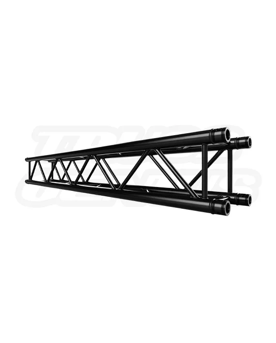
EVT290S-215 Black | 7.05ft (2.15m)
$885.00 Original price was: $885.00.$590.00Current price is: $590.00.
EVT290S-215 Black — 2.15 Meter (7.05 ft) Medium-Duty Square Aluminum Conical Truss (Matte Black)
Dimensions
Overall Truss Length: 7.05 ft (2.15 m) Straight Segment
Overall Truss Width: 11.41 in (290 mm)
Construction
Material Type: Aluminum Alloy EN AW-6082 T6
Main Tubing: 1.96 in (50 mm) Outer Diameter with 0.078 in (2 mm) Wall Thickness
Brace Tubing: 0.78 in (20 mm) Diagonal Bracing with 0.078 in (2 mm) Wall Thickness
Finish & Features
Surface: Matte Black Powder Coat Finish
Certification: TUV certified
Connection Type: Conical Connection System (Includes Couplers, Tapered Pins, and R-Clips)
Compatibility: Fits F34, EVT290S, and all standard 290mm Square Truss systems
Weight: 31 lb (14.06 kg)
In stock
EVT290S Truss Systems Knowledge Center
2.15 m Matte Black Square Truss Straight Section.
For Aerospace Exhibits, Defense Displays, Lighting Grids, and Modular Technical Structures.
The EVT290S-215 Black is a matte-black 2.15 m / 7.05 ft straight section for compatible EVT290S, F34, and matching 290 mm square entertainment-truss systems. Use this extended standard-length member where an aerospace exhibit, defense-industry display, military or government event environment, lighting grid, technical demonstration framework, stage structure, or other compatible planned truss layout calls for a 2.15 m straight run.
Identity and Core Facts
Straight Section Overview
2.15 m F34 Square Truss for Technical and Entertainment Systems.
The EVT290S-215 Black is a 2.15 m / 7.05 ft straight member for compatible 290 mm square truss systems. It supports controlled spacing in planned aerospace exhibits, defense contractor displays, military and government event infrastructure, technical demonstrations, lighting grids, stage structures, trade-show frames, and other compatible modular builds.
Aerospace, Military & Defense
Modular Frameworks for Technical Exhibits and Defense-Industry Events.
Use the EVT290S-215 Black as one component within a compatible, project-specific modular truss system for aerospace exhibits, defense contractor displays, military and government event environments, aviation product presentations, technical demonstrations, conference lighting grids, branded display areas, and temporary presentation structures. Its 7.05 ft length can help establish repeatable spacing in planned frameworks.
Applications
A 2.15 m Member for Exhibits, Technical Displays, and Production Systems.
Use the EVT290S-215 Black wherever a compatible 290 mm square-truss build calls for a 2.15 m / 7.05 ft section. The completed structure determines required supports, rigging method, loads, accessories, anchorage, and site approvals.
Series Construction
290 mm Square Truss with Conical Coupler Connections.
The EVT290S-215 Black carries the core construction of the EVT290S series in a 2.15 m straight section: a 290 x 290 mm square profile, 50 mm main chords, 20 mm diagonal braces, EN AW-6082 T6 aluminum, matte-black powder coat, and conical end connections.
Included Connection Hardware
What Ships with the EVT290S-215 Black.
Each straight section ships with the connection hardware used to join it to compatible conical-receiver components. Confirm the project component schedule before assembly; a finished structure may also require longer sections, corners, base plates, clamps, ballast, rigging hardware, and other project-specific items.
Technical Reference
Product Specifications.
Identification
Product Details
Dimensions
Section Size
Construction
Tube and Material Data
Connection Set
Included Hardware
System Compatibility
Match the Truss Profile and Connection Before You Build.
The EVT290S-215 Black is intended for compatible EVT290S, F34, and matching 290 mm square truss systems using conical connections. Similar appearance alone does not establish compatibility. Confirm the receiver spacing, coupler fit, chord spacing, alignment, and applicable system documentation before assembly.
Connection and Inspection
Confirm Fit First. Then Seat, Pin, and Retain.
Once receiver spacing and compatible hardware are confirmed, assemble the connection in this order. Prepare the current project drawing, compatible mating components, supplied connection hardware, and approved support or rigging plan. Assemble on a stable work surface with access to inspect every receiver and pin location.
Engineering Reference
Load-Span Reference for Completed Truss Runs.
All truss loading calculations are based on a completed compatible 290 mm square-truss run supported or suspended at both ends: static loading only; loads applied at approved truss panel points; truss self-weight included in the listed capacities; spans may consist of different truss lengths; and bending-moment and shear interaction at truss connections is considered. Values are limited by strength and reduced per ANSI E1.21.
| Load Case | Unit | 2.0 m | 2.5 m | 3.0 m | 3.5 m | 4.0 m | 4.5 m | 5.0 m | 5.5 m | 6.0 m | 6.5 m | 7.0 m | 7.5 m | 8.0 m | 8.5 m | 9.0 m | 9.5 m | 10.0 m | 10.5 m | 11.0 m | 11.5 m | 12.0 m |
|---|---|---|---|---|---|---|---|---|---|---|---|---|---|---|---|---|---|---|---|---|---|---|
| Span | ft | 6.56 | 8.20 | 9.84 | 11.48 | 13.12 | 14.76 | 16.41 | 18.05 | 19.69 | 21.33 | 22.97 | 24.61 | 26.25 | 27.89 | 29.53 | 31.17 | 32.81 | 34.45 | 36.09 | 37.73 | 39.37 |
| Center Point Load (CPL) | lb | 1,360 | 1,265 | 1,170 | 1,075 | 980 | 905 | 830 | 755 | 680 | 640 | 595 | 555 | 510 | 484 | 460 | 435 | 410 | 390 | 375 | 360 | 340 |
| Deflection | in | 0.09 | 0.14 | 0.20 | 0.25 | 0.30 | 0.39 | 0.47 | 0.56 | 0.65 | 0.77 | 0.89 | 1.01 | 1.13 | 1.30 | 1.47 | 1.64 | 1.81 | 2.04 | 2.27 | 2.50 | 2.73 |
| Third Point Loads (TPL) | lb | 810 | 765 | 725 | 680 | 640 | 595 | 555 | 510 | 470 | 450 | 435 | 415 | 400 | 370 | 340 | 310 | 280 | 265 | 245 | 230 | 215 |
| Deflection | in | 0.08 | 0.14 | 0.21 | 0.27 | 0.34 | 0.44 | 0.54 | 0.64 | 0.74 | 0.91 | 1.09 | 1.27 | 1.45 | 1.61 | 1.77 | 1.93 | 2.08 | 2.28 | 2.47 | 2.67 | 2.86 |
| Quarter Point Loads (QPL) | lb | 510 | 505 | 500 | 490 | 485 | 455 | 420 | 390 | 355 | 330 | 305 | 280 | 255 | 240 | 230 | 215 | 205 | 195 | 185 | 170 | 160 |
| Deflection | in | 0.07 | 0.14 | 0.21 | 0.28 | 0.35 | 0.47 | 0.58 | 0.70 | 0.81 | 0.94 | 1.07 | 1.19 | 1.32 | 1.52 | 1.73 | 1.94 | 2.14 | 2.36 | 2.58 | 2.79 | 3.01 |
| Uniformly Distributed Load (UDL) | lb/ft | 230 | 202 | 174 | 147 | 119 | 107 | 94 | 82 | 70 | 61 | 53 | 45 | 37 | 33 | 30 | 27 | 24 | 22 | 20 | 19 | 17 |
| Deflection | in | 0.06 | 0.12 | 0.18 | 0.24 | 0.30 | 0.43 | 0.56 | 0.69 | 0.82 | 0.94 | 1.06 | 1.18 | 1.30 | 1.50 | 1.71 | 1.91 | 2.11 | 2.35 | 2.59 | 2.83 | 3.07 |
Table assumptions: The reference evaluates unbraced truss configured as a simply supported beam. The primary analyzed spans were 2 m, 4 m, 6 m, 8 m, 10 m, and 12 m; intervening published values are interpolated. If CPL, TPL, or QPL loading occurs at a truss connection, a minimum of two chords is assumed to support the vertical load.
Not included: Shock loads, dynamic loads, and resultant horizontal rigging forces, including forces from bridles or baskets. UDL applies only when the load is evenly distributed across the entire span. Published load cases are alternatives and are not additive.
Licensed structural-engineer review is required for every truss system. These values are general planning reference only and do not approve or rate an individual straight section, a completed lighting plot, a ground-support structure, a goal post, a tower, a start/finish arch, a suspended configuration, an outdoor installation, a mixed-component build, or any other assembled truss system. Confirm the complete configuration, supports, connections, span, applied loads, attachment points, rigging, ballast or anchorage, environmental conditions, and applicable code requirements with a licensed structural engineer before use.
Current documentation: Product specifications, included hardware, compatibility information, and availability are subject to change. Verify current product drawings, manufacturer instructions, connection hardware, and applicable engineering information before ordering, assembling, or using this product.
System Responsibility
Capacity Comes from the Completed Configuration.
This 7.05 ft / 2.15 m section does not establish an independent span or load rating for a finished structure. Determine capacity from the complete arrangement, including connected components, span, orientation, supports, attachment locations, rigging method, applied loads, lighting, video, scenic equipment, environmental exposure, and any site-specific aerospace, military, defense, government, or aviation requirements.
Frequently Asked Questions
EVT290S-215 Black Questions.
Why choose a 7.05 ft / 2.15 m straight truss section?
Choose this section when a compatible 290 mm square-truss design calls for a 2.15 m member. It provides controlled spacing for longer lighting grids, aerospace exhibits, defense-industry displays, technical presentation systems, and compatible modular structures.
Can this truss be used for aerospace or defense applications?
It may be used as one component of a compatible completed truss system for approved aerospace exhibits, defense contractor displays, military or government event environments, and technical demonstrations. Those end-use references do not mean the product is flight-certified, military-qualified, tactical rated, or approved for a particular government or defense application.
What does the load-span reference apply to?
It applies only to a completed compatible 290 mm square-truss run configured as a simply supported beam under the published assumptions. It does not independently rate this section, a goal post, a tower, a ground-support system, an outdoor structure, or a mixed-component assembly. A licensed structural engineer must review every truss system before use.
What conical connection hardware is included?
Each EVT290S-215 Black section includes 4 conical couplers, 8 coupler pins, and 8 r-clips for compatible conical connections.
Planning an aerospace, defense, or technical truss system?
Contact us for matching straight sections, corners, base plates, compatible 1.96 in / 50 mm clamps, current technical documents, quantity pricing, and project coordination.
Structural Solutions, Unmatched Innovation