
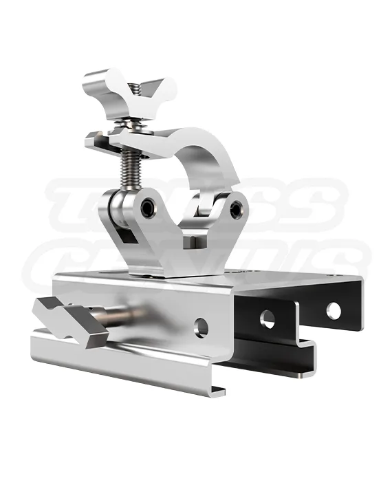
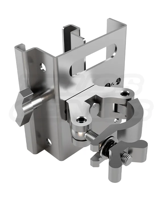
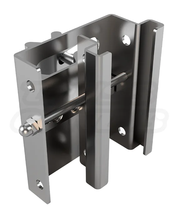

EVT50C-TNTCNC
$249.00 Original price was: $249.00.$199.00Current price is: $199.00.
EVT50C-TNTCNC
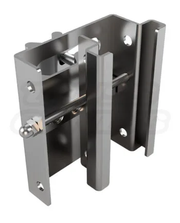
Adjustable Steel Tent Beam Clamp — Engineered for I-beams, Keder tent tracks, and standard structural rails
Dimensions & Specs
Adjustment Range: 40–130 mm (Operating range: 50–110 mm)
Pre-Threaded Holes: M10 (x2), M12 (x2), and M14 (x1)
Tightening Mechanism: S-Handle
Overall Dimensions: 135.5 mm W x 150 mm H x 53.8 mm D
Construction & Features
Material Type: Q235 Carbon Steel
Surface: Brushed Finish
Safe Working Load: 220 lb (100 kg)
Weight: 1.76 lb (0.80 kg)
In stock
Beam Clamp and Rigging Hardware Knowledge Center
EVT50C-TNTCNC Adjustable Steel Beam Clamp.
A 220 lb / 100 kg Rated Attachment Point for Compatible I-Beams, Keder Tracks, and Structural Rails.
The EVT50C-TNTCNC is an adjustable Q235 carbon-steel beam clamp for compatible steel and aluminum I-beams, Keder tent tracks, and structural rails. Its jaw adjusts from 40–130 mm, with a stated operating range of 50–110 mm for the listed beam and rail applications. Five pre-threaded holes—two M10, two M12, and one M14—provide attachment positions for compatible hardware. The published safe working load is 220 lb / 100 kg for the clamp-to-beam connection; the complete assembly is limited by its lowest-rated component and must be verified for the actual beam, attachment, load path, and installation.
Product Facts
Product Overview
An Adjustable Beam Clamp for Compatible Flat-Flange Support Members.
The EVT50C-TNTCNC provides an adjustable clamp interface where a compatible I-beam flange, Keder track profile, or structural rail is used instead of round truss tubing. The clamp’s body, jaw, S-handle, and threaded holes create a hardware interface; they do not independently approve a fixture, rigging plot, building beam, tent structure, rail, or overhead installation.
Common Applications
For Planned Attachment Points on Compatible Beams, Tracks, and Rails.
Use the EVT50C-TNTCNC where a qualified installation plan calls for a clamp-mounted attachment point on a compatible flat-flange structural member. The actual beam, track, rail, fasteners, fixture, and complete load path must be evaluated before installation.
Construction Details
Q235 Carbon Steel Construction with Adjustable and Threaded Interfaces.
The clamp body is documented as Q235 carbon steel with a brushed finish. Its compact profile and threaded attachment points support hardware planning in locations where an appropriate round-tube clamp cannot seat. Verify actual flange width, structural member condition, thread fit, attachment hardware, and the complete load chain before use.
Threaded Hole Options
Five Pre-Threaded Holes for Compatible Hardware Selection.
The clamp provides two M10 holes, two M12 holes, and one M14 hole. Use only hardware with the matching thread specification, appropriate engagement, and a verified load rating. A matching thread does not by itself establish that an eye bolt, shackle, hook, clamp, fixture yoke, or other attachment is suitable for the installation.
Technical Reference
EVT50C-TNTCNC Product Specifications.
Identification
Product Details
Dimensions and Adjustment
Physical Reference
Attachment Interfaces
Threaded Hole Pattern
Rating and Support
Published Product Reference
Compatibility and Fit
Verify the Actual Flange. Do Not Select by Name Alone.
The clamp is listed for steel and aluminum I-beams, Keder tent tracks, and most industry-standard rails within a 50–110 mm range. Verify the actual measured flange width and profile before ordering and again before installation. The clamp must not be used where the jaw cannot close securely, make even contact, or remain fully seated on a clean and undamaged support surface.
Installation Checks
Measure the Flange. Seat the Jaw Fully. Verify the Load Path.
The clamp installation must be completed by personnel familiar with the support member, the intended load, and the required rigging or fixture-mounting practices. The following sequence provides product-level checks; it does not replace a project-specific rigging plan, structural review, or venue approval.
Safety and Engineering
220 lb / 100 kg Applies to the Clamp Connection. The Assembly Is Limited by Its Lowest-Rated Component.
The stated 220 lb / 100 kg safe working load applies to the clamp-to-beam connection. The safe capacity of the completed assembly is limited by the lowest-rated component in the load chain, including the beam or track, clamp, threaded fastener, eye bolt, shackle, hook, fixture, truss clamp, secondary safety, and the supporting structure. Do not exceed the published safe working load or treat the clamp purchase as approval of a specific installation.
Evidence and Review
What This Page Confirms, and What the Installed Assembly Must Still Establish.
This page confirms the documented product facts: Q235 carbon-steel construction, 40–130 mm adjustment, 50–110 mm operating range, five threaded holes, S-handle tightening, 135.5 x 150 x 53.8 mm dimensions, 1.76 lb weight, 220 lb safe working load, TUV Rheinland certification, and listed beam, track, and rail applications. It does not establish the suitability or capacity of a specific beam, tent track, rail, fixture, fastener, rigging plot, or complete installation.
Product Questions
Frequently Asked Questions.
What beam widths and profiles does the EVT50C-TNTCNC fit?
The clamp has a 40–130 mm jaw adjustment range and a stated 50–110 mm operating range for listed steel and aluminum I-beams, Keder tent tracks, and standard structural rails. Measure the actual flange width and verify the profile before ordering and installation.
What can attach to the threaded holes?
The five holes include two M10, two M12, and one M14 thread. Use matching threaded hardware with adequate engagement and a verified rating. The source identifies the M12 interface for direct pairing with the EVT50C-BEHNC clamp.
What does the 220 lb / 100 kg safe working load mean?
It is the published safe working load for the clamp-to-beam connection. The total assembly is limited by the lowest-rated item in the complete load chain, including the support member, clamp, hardware, fixture, and secondary safety.
Can I use this clamp for overhead rigging?
Overhead use requires a verified load path, properly rated components, full jaw contact, a correctly tightened S-handle, required secondary safety, and any applicable project, venue, or engineering review. Product purchase does not approve a specific installation.
Can I use it on a Keder tent track?
It is listed for compatible Keder tent tracks within the stated operating range. Confirm the specific track profile, tent-system requirements, permitted attachment method, loading, and complete support arrangement before use.
How should the clamp be inspected?
Inspect the jaw, S-handle, threads, and attached hardware before every use. Do not use the clamp if it is damaged, deformed, corroded, has thread damage, or cannot close fully and evenly on the support member.
Is a 3D model available?
Yes. The product source identifies a GLB 3D model for general visualization. It is not a load-rating, fit-verification, or safety-critical planning document.
Need to mount equipment from a compatible beam, track, or structural rail?
Contact us for flange-range confirmation, thread and companion-clamp guidance, hardware planning, load-path coordination, CAD resources, engineering support, and quantity pricing.
Structural Solutions, Unmatched Innovation